Design the signal chain
Selected an accessible antenna, amplification, filtering, and software-defined-radio architecture around the 21-cm line.
Radio astronomy · Instrumentation
A low-cost signal chain built, measured, and used to detect neutral hydrogen in the Milky Way near 1420 MHz.
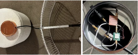
Project overview
The 1420 MHz hydrogen line is produced when the proton and electron spins in a hydrogen atom flip relative to one another. The transition is rare for an individual atom, but neutral hydrogen is abundant enough for the line to be observed across the Milky Way.
I designed and built a receiver to detect that line while keeping the total project cost below $250. The work included the antenna and receiver layout, a custom microstrip band-pass filter, NanoVNA testing, RF shielding, SDR software, and the final observation.
My contribution
Selected an accessible antenna, amplification, filtering, and software-defined-radio architecture around the 21-cm line.
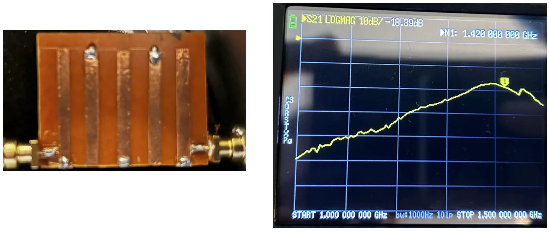
Used a NanoVNA to characterize each microstrip prototype, iterating the layout until the passband centred near 1.42 GHz. Insertion loss remained high at −18.39 dB, which the low-noise amplifier ahead of the filter had to absorb.
Recovered neutral-hydrogen emission from the Milky Way and observed a slight blueshift in the measured spectrum.
Design and testing
Set the bandwidth, gain, and filtering requirements around the 1420 MHz hydrogen line.
Choose the antenna, amplifiers, SDR, and fabrication materials while keeping the project below $250.
Fabricate the microstrip prototypes and measure each response with the NanoVNA.
Assemble the shielded receiver and measure the Milky Way’s hydrogen-line spectrum.
Full build record
The sections below contain the original component list, filter-design notes, build milestones, results, and project video.
System architecture

Band-pass filter
The filter began as a conventional capacitor-and-inductor design. I converted it to a microstrip equivalent, created rapid prototypes with single-sided copper PCB and copper tape, then characterized each prototype with the NanoVNA.
The final prototype centred at 1.42 GHz with an insertion loss of −18.39 dB. That is high for a receiver band-pass filter, and it is the clearest limitation of the build: hand-fabricated copper-tape microstrip on single-sided PCB cannot hold the tolerances a milled or commercial filter would. It was low enough, with the low-noise amplifier placed ahead of it, to recover the hydrogen line — but a milled board is the obvious next iteration.
Project milestones
Final result & future work
The project detected the neutral-hydrogen line with a slight blueshift, indicating relative velocity between Earth and the observed region of the Milky Way. At under $250, the system provides an accessible entry point into radio astronomy.
A future filter redesign could target other bands, including frequencies used by weather satellites, and extend the same build-and-measure workflow to new observations.